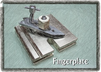
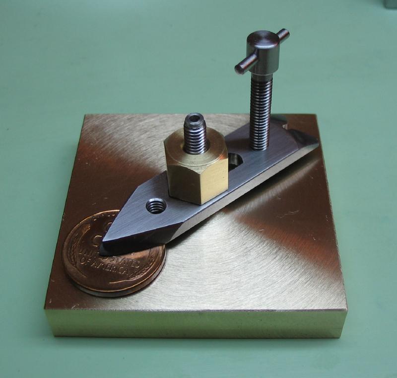
Drill Press Clamping Fixture - 'Fingerplate'
When using the drill press, it is good practice to clamp the work by some means. Holding work freehand is difficult to keep aligned and secure, and often results in incorrectly positioned holes, broken drill bits, or worse should the drill 'catch' the work. A common homemade solution to assist in this effort is a fingerplate. It consists of a flat, squared surface with a clamp ('finger)'. The shape of the finger piece and the surface are cut away to provide various means of holding and positioning work for drilling. The clamp is secured by a central stud and a counterscrew.
Plans for these tools can be found in various books and websites, but are usually too large for use on the Cameron drill press. I am following the basic design described by John Wilding in "Tools for the Clockmaker and Repairer." However, it was made to somewhat smaller dimensions and from metal stock that was on hand.
Plans for these tools can be found in various books and websites, but are usually too large for use on the Cameron drill press. I am following the basic design described by John Wilding in "Tools for the Clockmaker and Repairer." However, it was made to somewhat smaller dimensions and from metal stock that was on hand.
The clamp finger
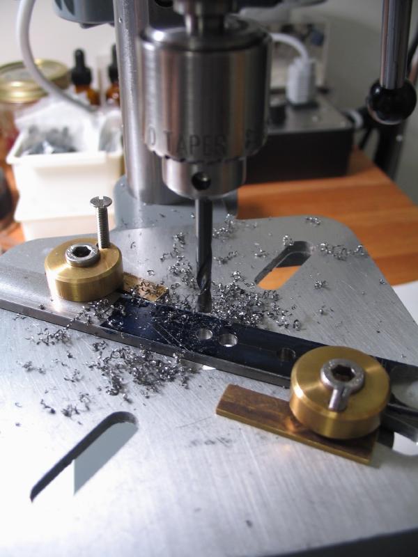
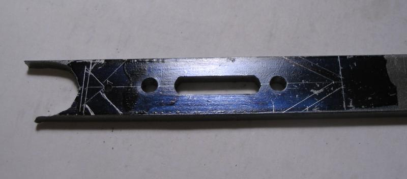
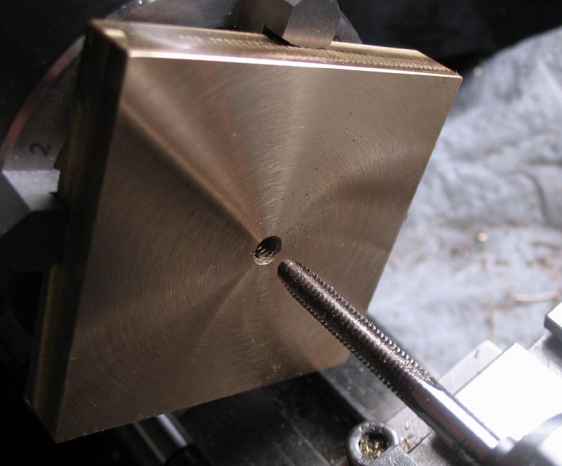
A piece of 1/8" x 1/2" mild steel flat bar was marked out and center punched. It is clamped to drill press table and center drilled to assure position and then drilled. There are two tapped holes for the leveling screw (M4x0.7) and two starting holes for the center slot to pass the base stud screw (4mm).
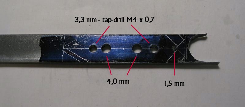
The 4mm holes are connected by sawing out with a piercing saw and evened out with a file.
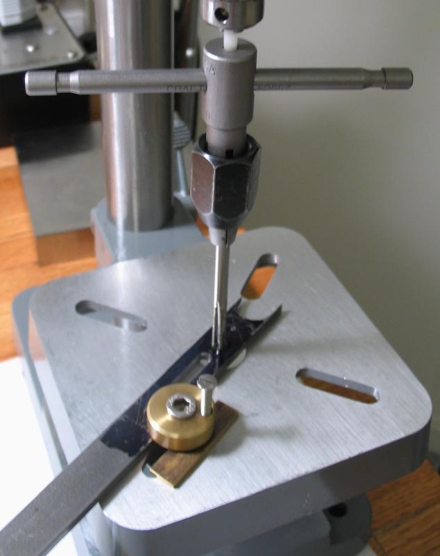
The holes are tapped M4x0.7.
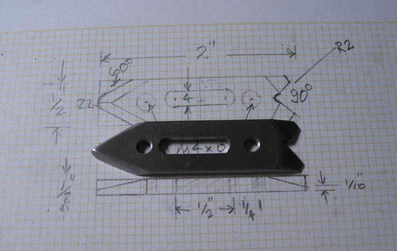
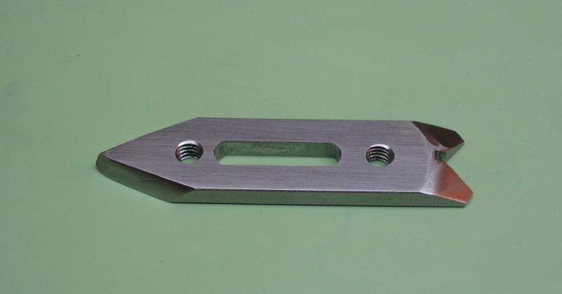
The basic shape is then sawed out and finished with files. It can then be touched up with emery paper.
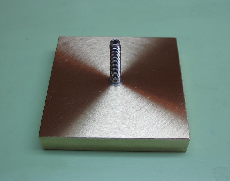
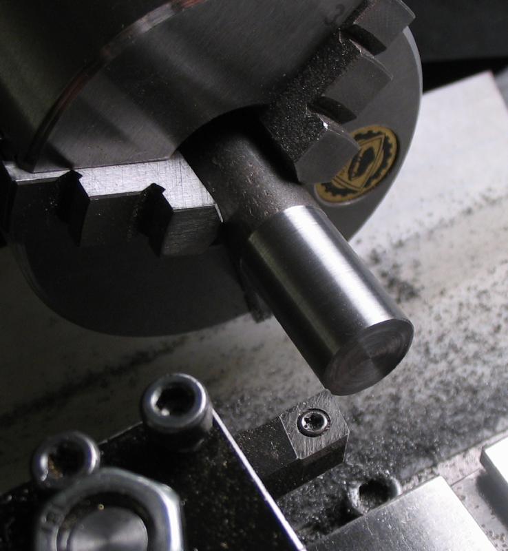
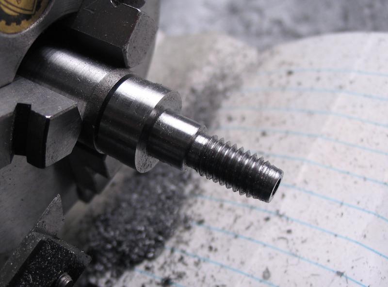
Stud Screw
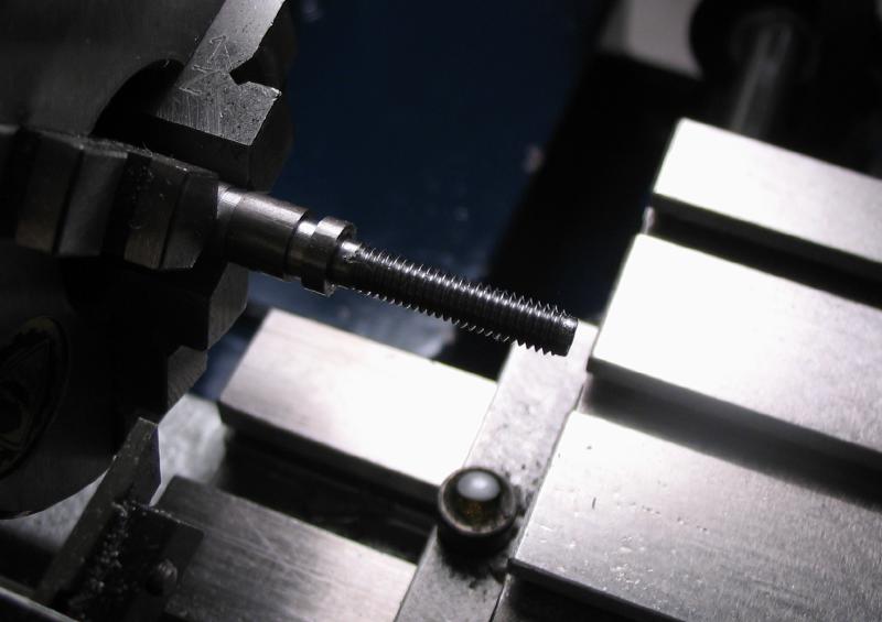
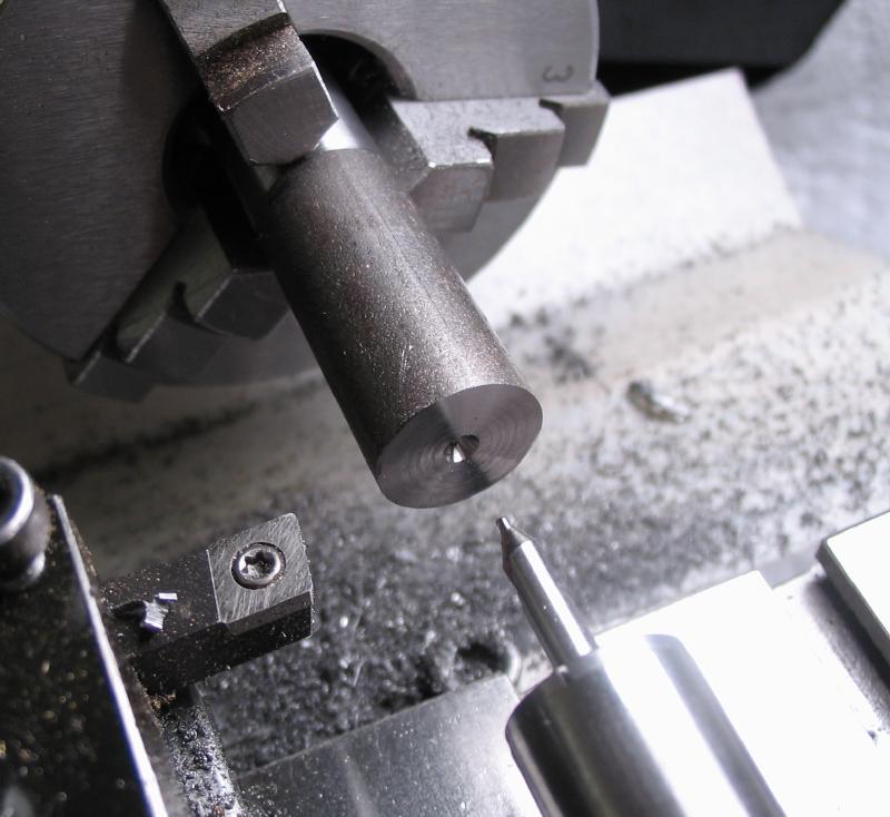
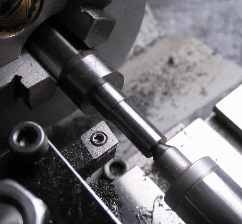
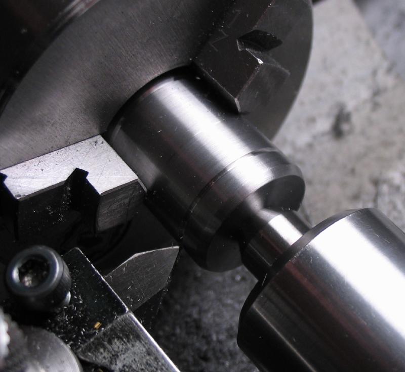
The clamp is secured by a stud screw which is mounted directly in the base plate. It was turned from 1/4" mild steel (12L14). A length of 20mm was reduced and threaded M4x0.7. The parting tool was used to mark out the flange. The rod was center drilled for tailstock support.
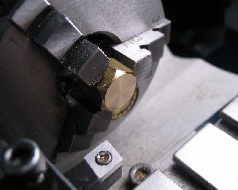
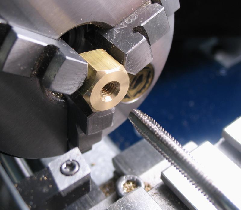
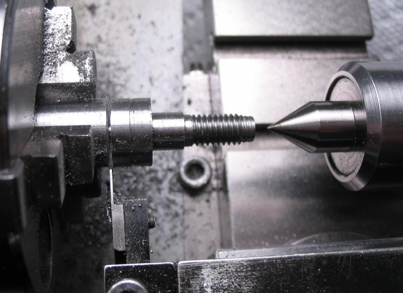
The work needed to be reversed to thread the other end. A holder was made from 1/2" diameter hex rod. It was faced on each end and chamfered. It was center drilled and drilled 3.3mm for tapping M4x0.7, and countersunk.
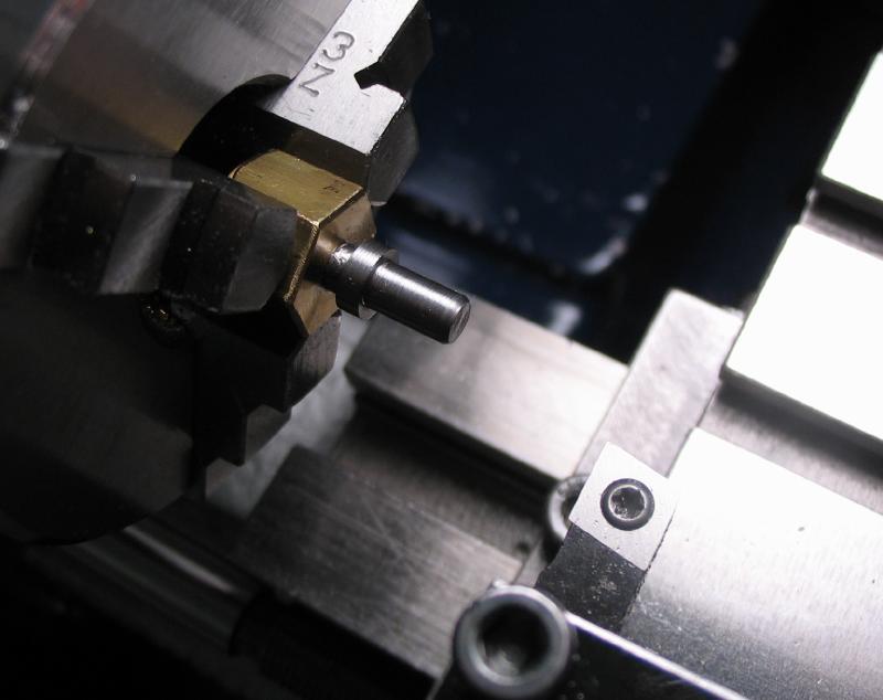
The stud could be mounted and turned on the reverse end to also be threaded. After threading, it was not easy removing the stud from the hex nut. Some brute force was used, and tool marks can be seen, left from the dreaded pliers.
Some care was given to making the hex nut, since it will become one of the components of the finished tool.
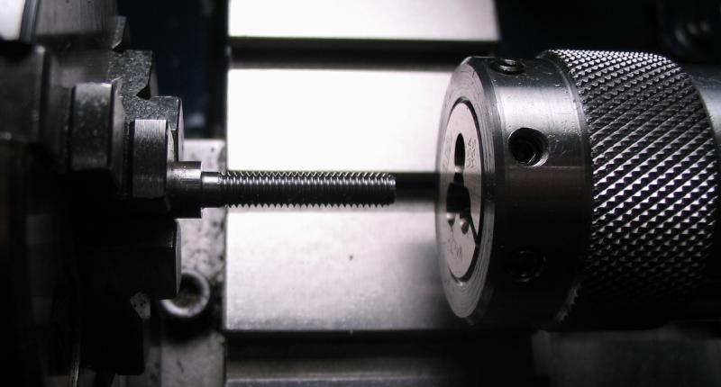
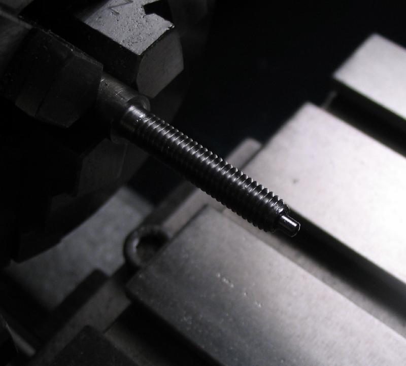
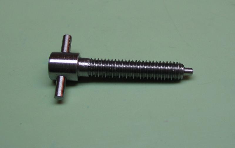
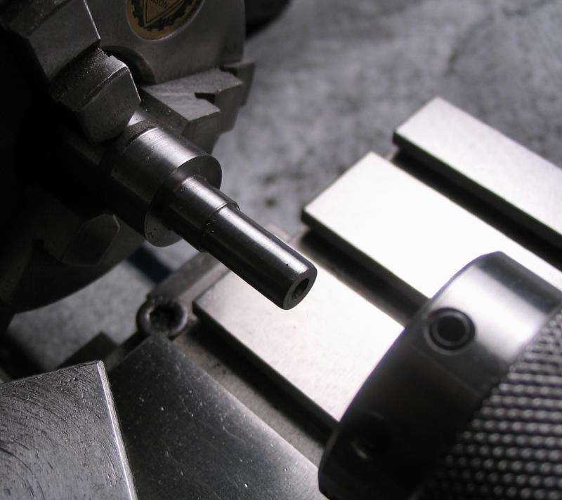
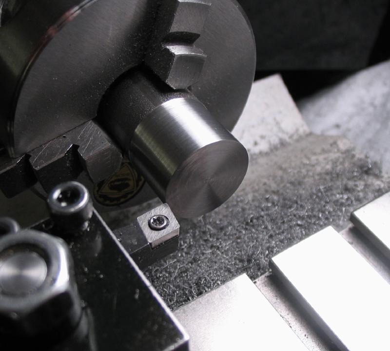
Counterscrew
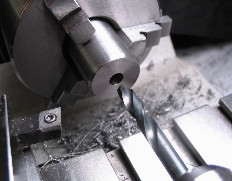
The counterscrew was also made from the same 1/4" mild steel rod. Also turned and threaded M4x0.7. Since it was center drilled for tailstock support, after turning, it was drilled 1/16". A piece of 1/16" O-1 drill rod was tapped into place and with a file it was smoothed over and polished with emery paper.
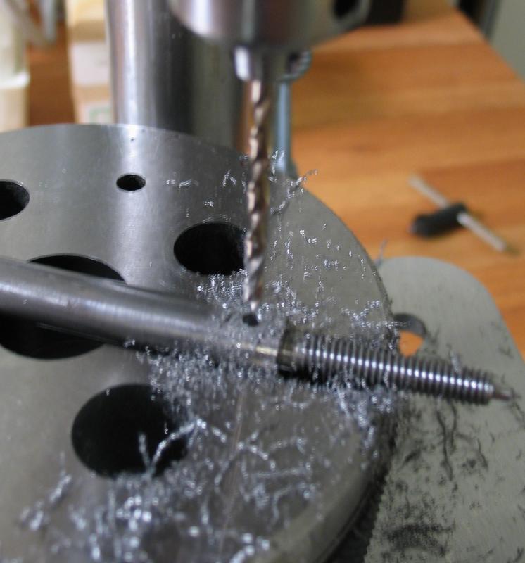
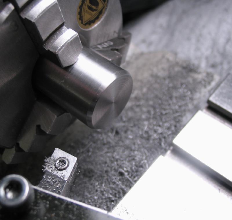
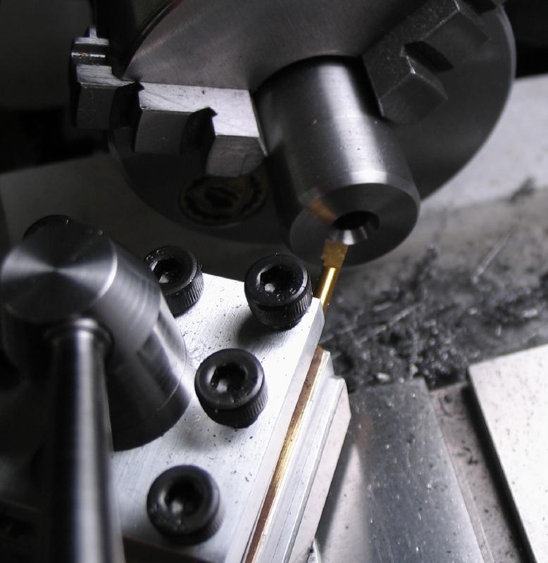
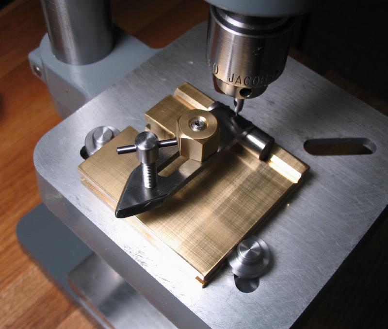
The rod was then cross drilled 1.9mm on the drill press using the toolmakers block for support.
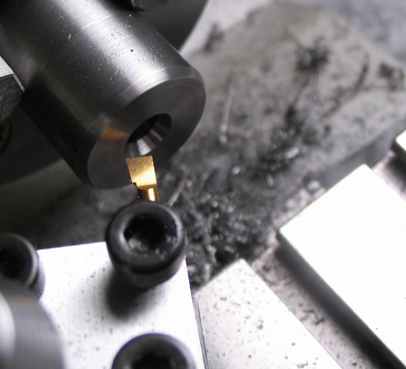
The rod was then returned to the lathe and the head reduced to 6mm and parted off.
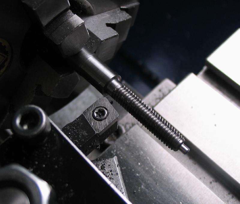
The cross drilling was broached open from each side until a piece of 2mm drill rod binds in the middle. It could then be tapped in with a small hammer.
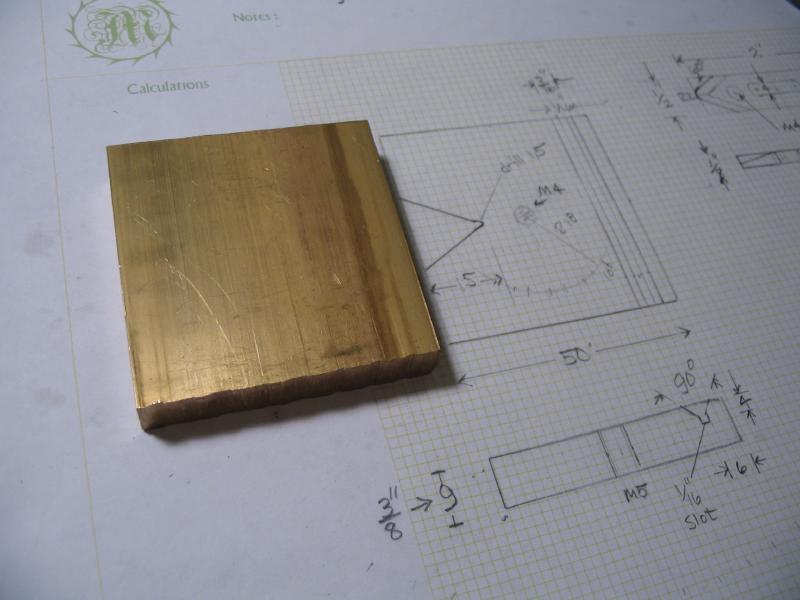
Base Plate
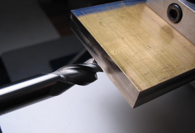
The base was started by hacksawing a 2" length of 2"x3/8" brass bar. It was mounted in the machine vice and squared on all sides with an endmill.
 |
 |
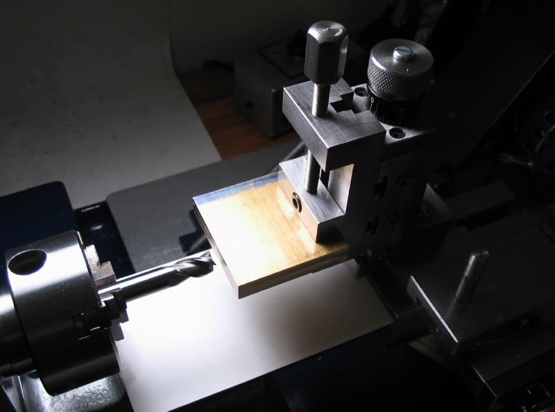
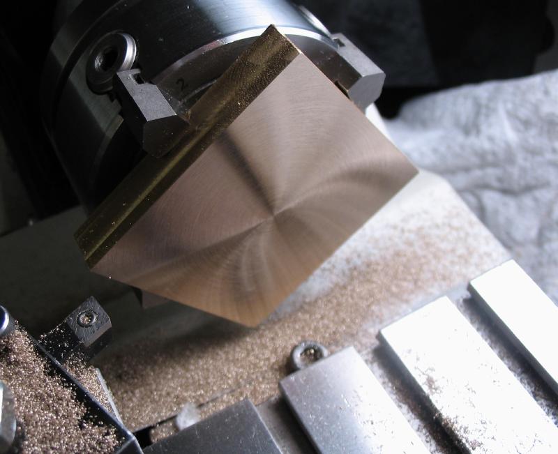
The faces were squared up in the 4-jaw chuck.
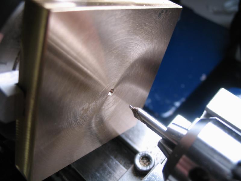
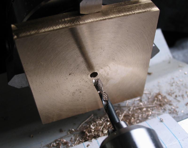
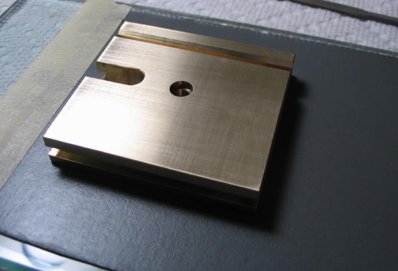
After facing the second side, the plate was center drilled and drilled 3.3mm for tapping M4x0.7.
The hole was then counterbored with a boring tool to mate with the flange of the stud screw.
 |
 |
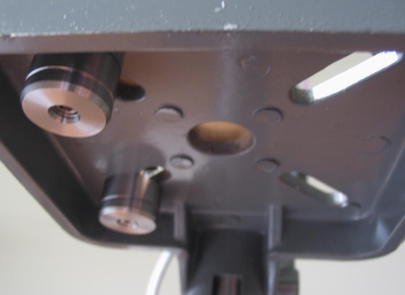
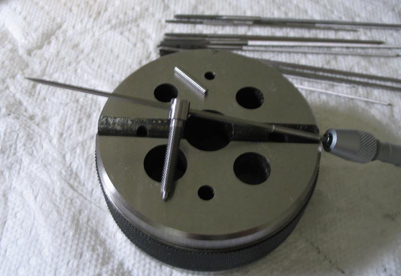
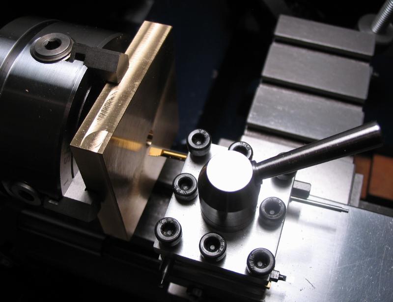
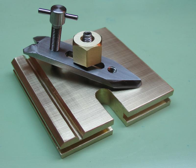
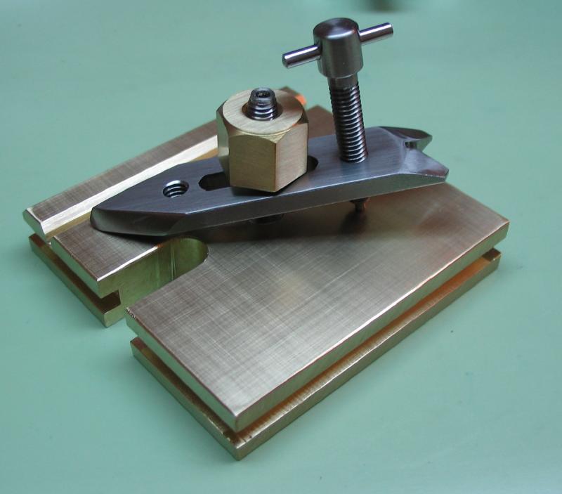
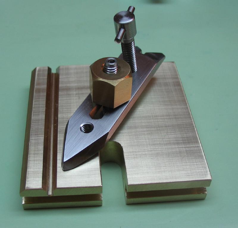
The various components can be tested for fit and function.
The base will have a cutout for drills or taps, etc. to pass and a V-shaped trough to hold round work. When drilling small delicate components, a sacrificial surface is sometimes helpful. Ultimately the fingerplate base should be accepted as being expendable.
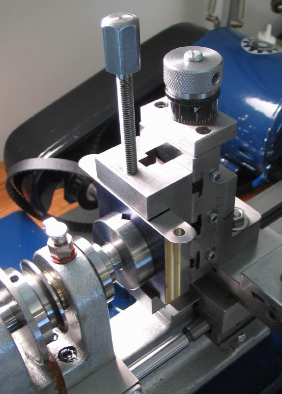
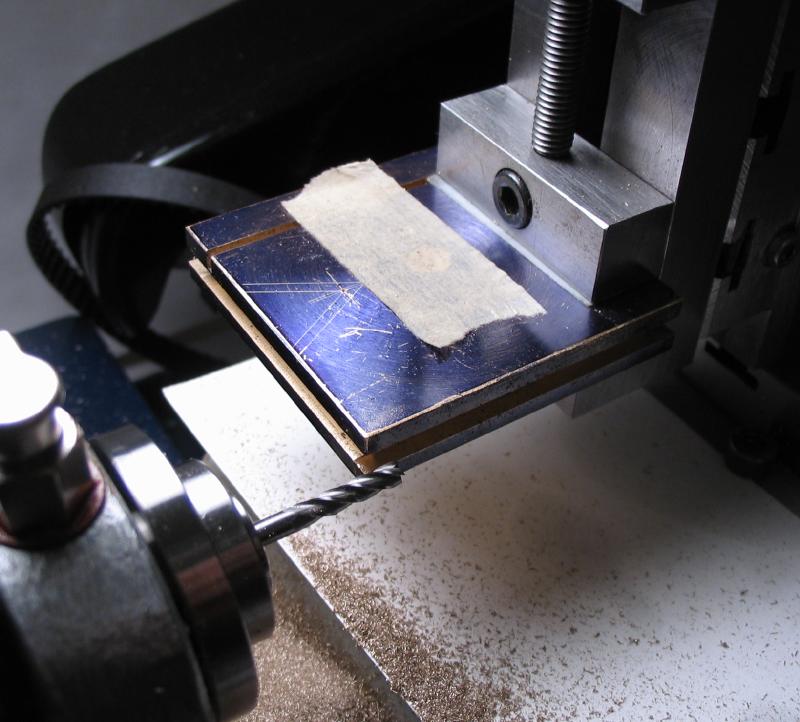
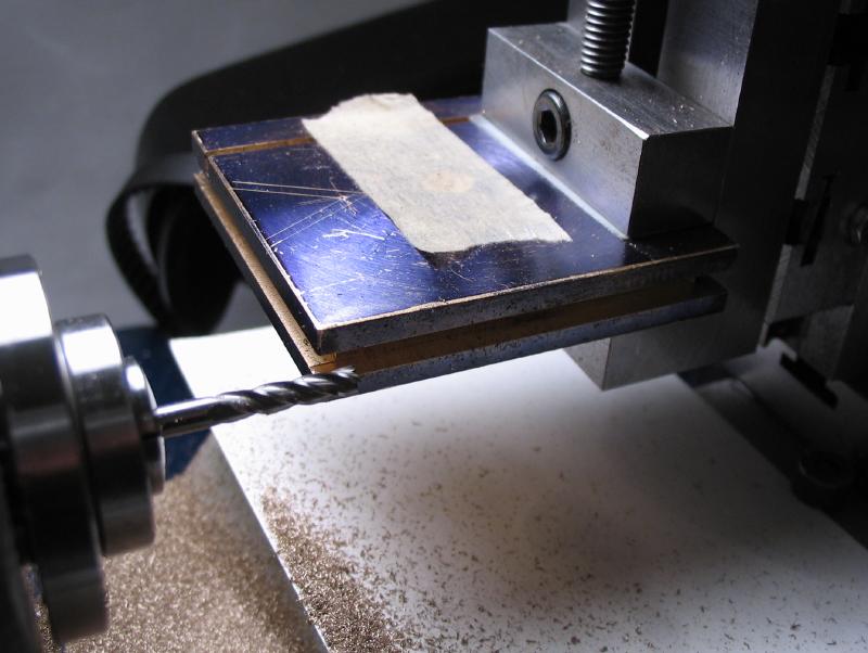
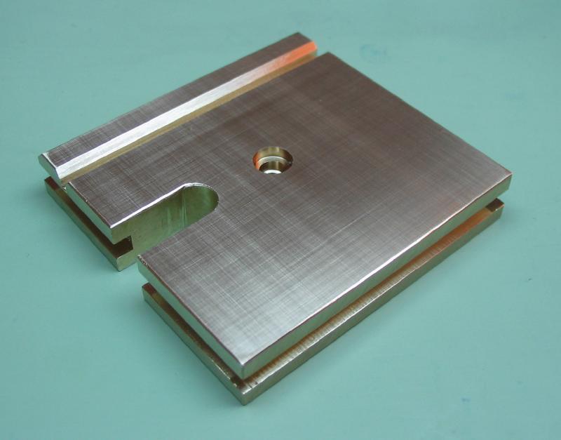
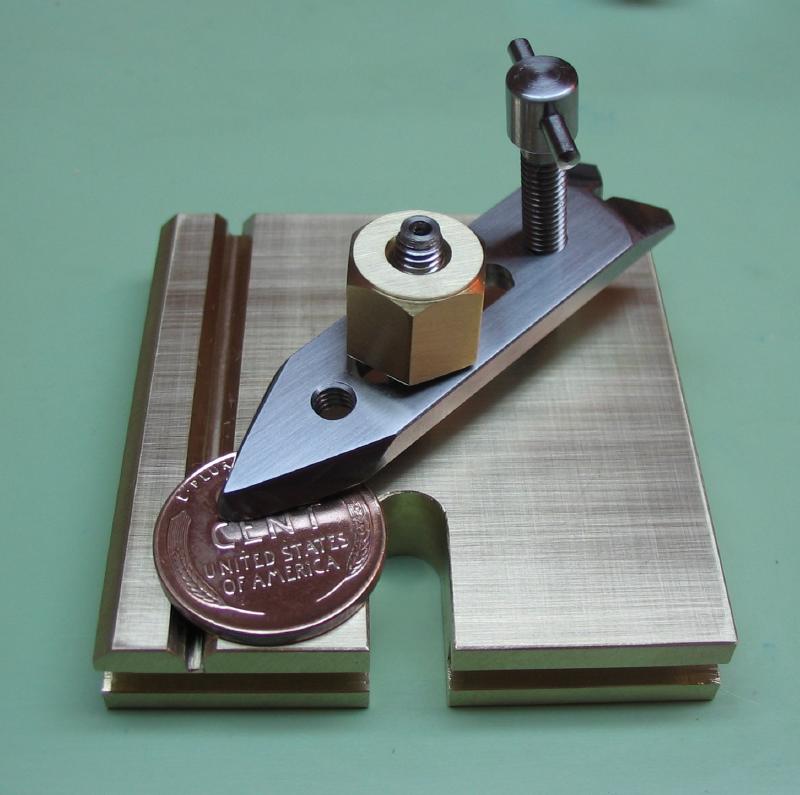
The plate was mounted in the machine vice. The clamping bar in the vice needed to be removed to fit the baseplate, and a piece of feeler gauge was used to provide some distribution of force. The central channel for the V-slot was milled with a 1.5mm endmill to a depth of 3mm.
A 3mm x 3mm channel was milled around the periphery of the base. This will be used for clamping the plate to the drill press's work table.
 |
 |
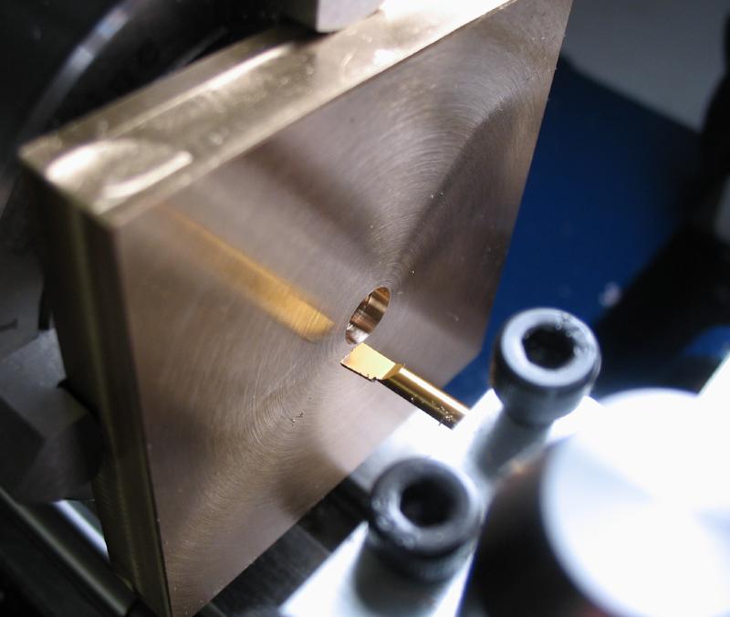
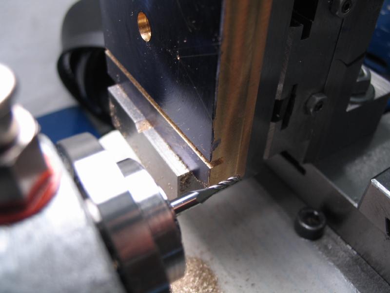
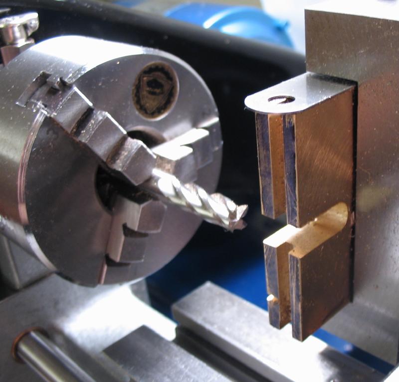
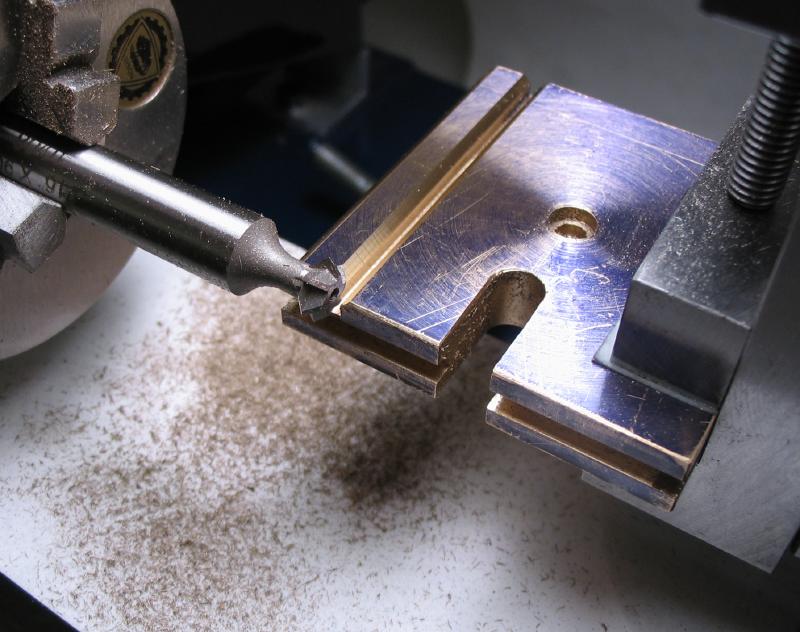
The work was again repositioned and a 1/4" slot milled into one side of the plate. This is the open space for clearance of drills and taps.
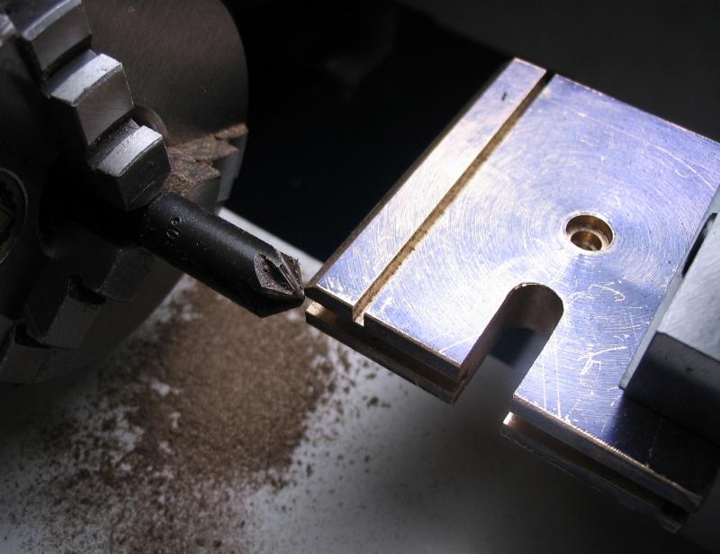
The edge was chamfered 45 degrees with a 90 degree countersink. This edge has no functional purpose, but was needed to clear the shank of the 90 degree double angle cutter that is used to mill the chamfers of the V-slot.
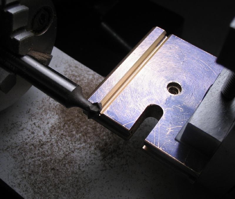
The 45 degree chamfers were then milled onto the top edge of slot.
Each edge is milled separately.
 |
 |
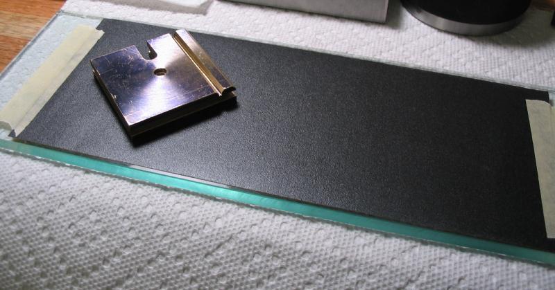
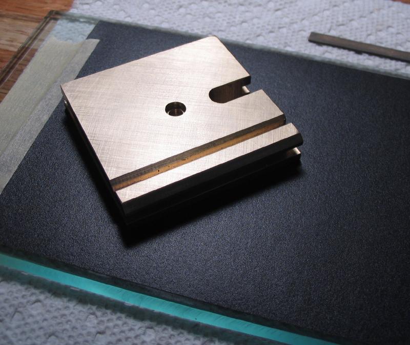
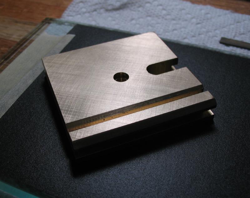
The plate was then polished up on emery paper. The paper was fixed on a glass plate. The work was started with 400 grit, followed by 600 grit. After each stroke, the work is rotated 90 degrees, this helps keep the plate true.
 |
 |
 |
 |
 |
 |
 |
 |
 |
 |
Clamping Screws
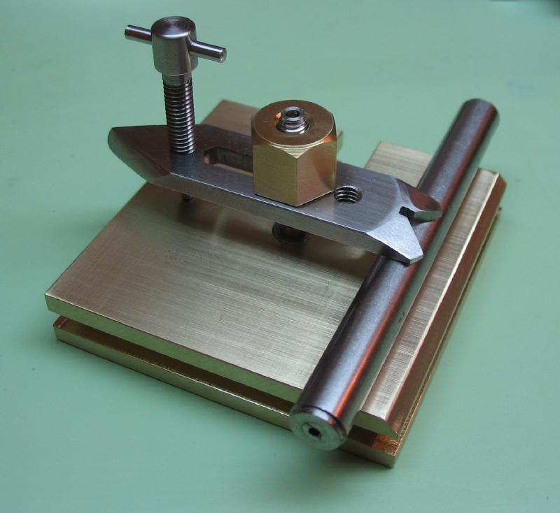
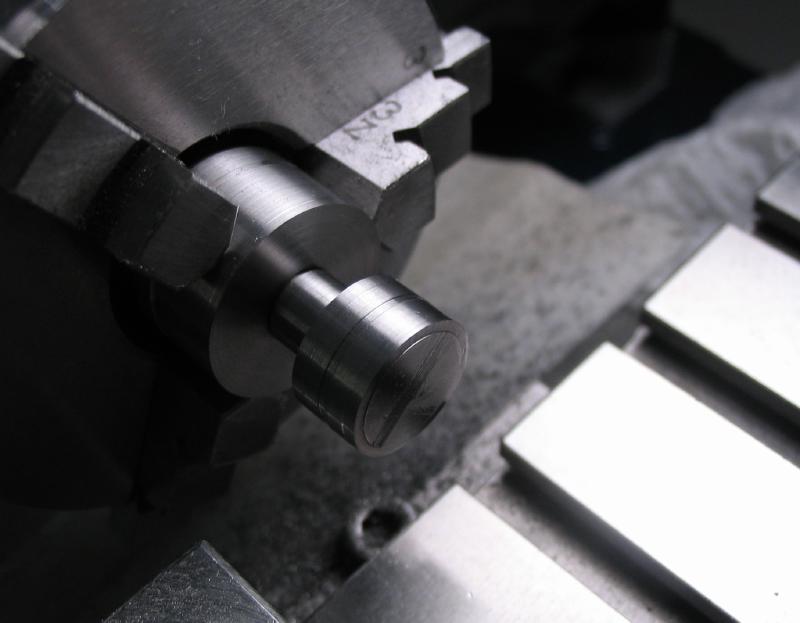
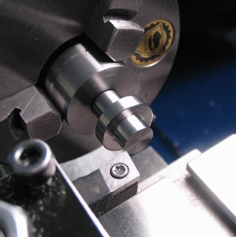
The plate can be secured to the drill press work table with T-screws. These are made from 1/2" mild steel. A length was turned true for holding in the chuck.
The rod was faced and center drilled. With tailstock support, the basic dimensions are turned.
A length of 12mm is threaded M6x1.0
The flange was started and the work parted.
 |
 |
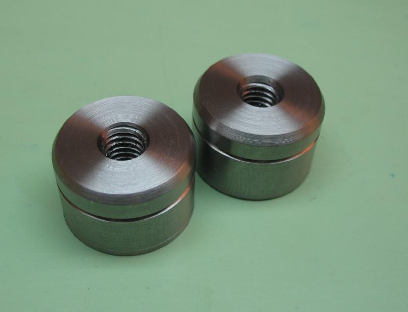
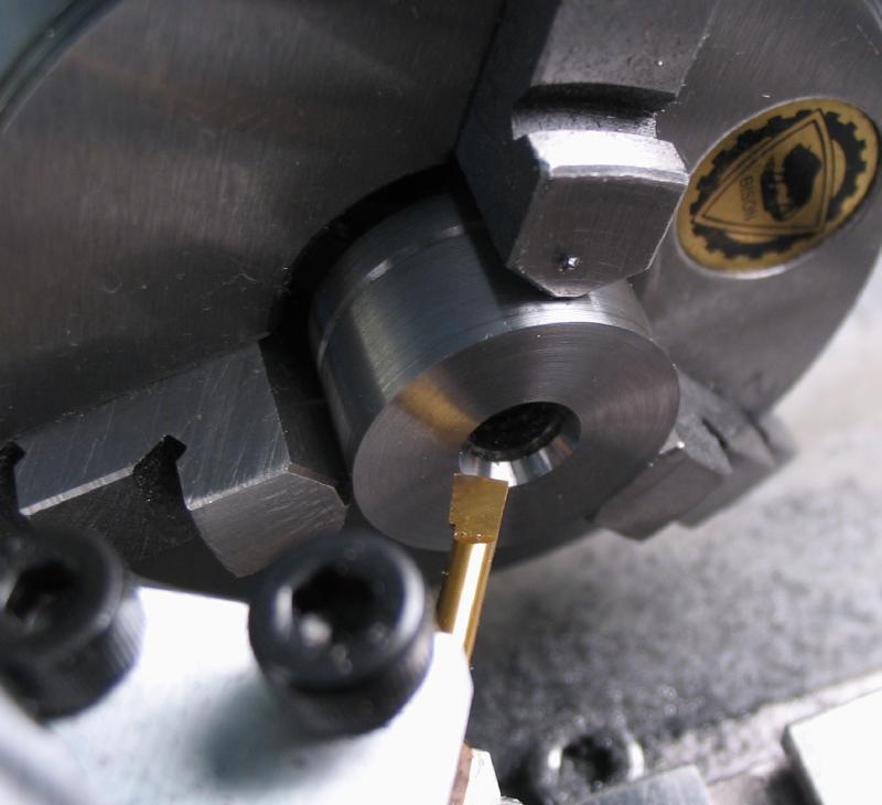
The screws will be secured with nuts from underneath the worktable, these can also be used to hold the parted screws on the lathe for finishing. The nuts are started as a pair from 3/4" mild steel. It is turned down to a true diameter and faced to a length of 1" (25.4mm). It is drilled 5mm and tapped M6x1.0.
A 60 degree countersink was bored to fit the tailstock center, this also assists in tapping.
 |
 |
A decorative groove was made with a 60 degree lathe tool.
The turning was repeated on the reverse end and the nuts are parted from each other. The taper tap was not quite long enough, so prior to parting, the threading was completed from the reverse side to complete the threads to full depth (note: there was enough of a thread started so that the tap could pick it up on the reverse side, so that the thread is continuous).
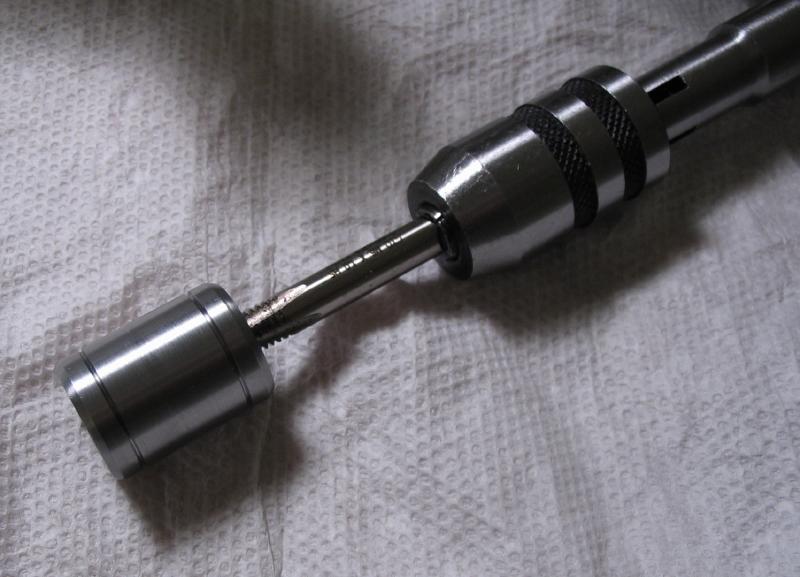
One of the nuts is returned to the 3-jaw to be faced and countersunk. The previously parted screw is secured into the nut and the final dimensions turned.
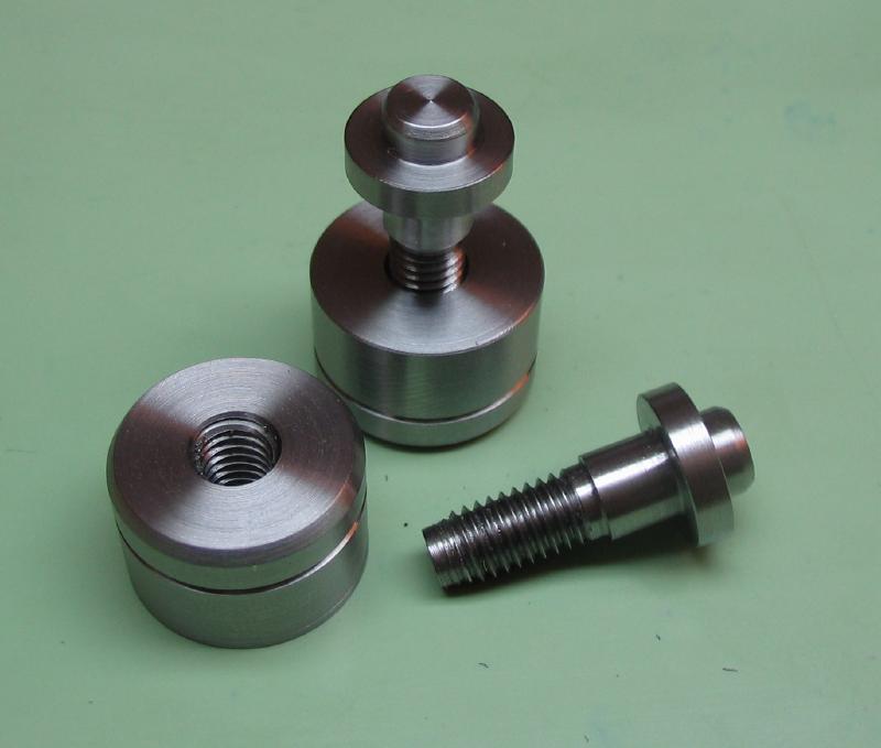
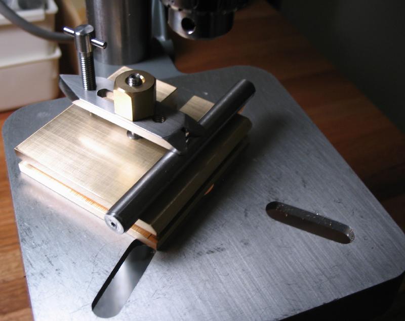
I considered another attempt at knurling or otherwise modifying the grip of the securing nuts, but when testing the fit on the drill press I found that the fingerplate was easily secured.